Planning
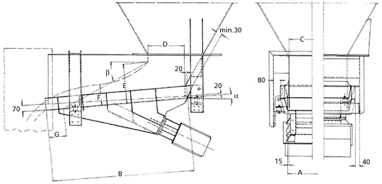
These guidelines apply mainly for the optimization of discharge flow from silos and bins through VICAL® vibrating conveyors.
The discharge capacity and the overall function of the vibratory feeder channel are normally dependent on the proper sizing of the discharge mouths of silos and bins. The discharge outlet and the vibratory feeder channel as a construction unit are schematically shown above.
The outlet or discharge mouth should be constructed in such a way that the feed of the vibratory channel with the bulk material from the silo is as continuous as possible. This constant flow can partly be achieved with the aid of VIMOT® or VIMAG® vibrators attached to the side walls of the silos, or by means of a vibrating discharge mouth. These applications are especially necessary when the material to be discharged tends to form spots and agglomerations inside the silo.
The following examples and guidelines will give the planner, without having to consult the manufacturer, the possibility to design and build the discharge mouth of the silo, thus facilitating the purchase of the appropriate vibratory feeder conveyor.
The figure above shows the construction features and sizing of a normal discharge mouth. The vibratory channel is mounted with an 8° inclination. With greater inclination, higher conveying velocities are achieved, but one must take into account here greater degradation of the material to be conveyed, i.e., the material composition will deteriorate, and there will be no homogeneity in the material flow. If this is not relevant, the trough can be inclined up to 15°. Above this the material flow is no longer controllable because material slides occur at higher velocities.
The mounting of the trough at the discharge mouth is done in front on rubber springs and steel cables for support (see diagram). The rubber springs and their respective supports and steel cables will be supplied with the vibratory channel.
The chute or, more explicitly, the supports for the rubber springs, can usually be attached to steel U-profiles. These in turn can be attached directly to the walls of the discharge mouth, since the mass of the silo is reasonably greater than that of the chute, the remaining vibrations will be absorbed by the silo. To avoid lateral deflections in the discharge mouth walls, another U-profile should be fixed transversally, only at the front, joined to the other two profiles and to the discharge mouth walls (see scheme above).
Mounting on racks independent of the silo is also possible, but often not feasible because of the space required below the rail.
The side flaps of the chute usually limit the height of the material to be conveyed, but this does not imply that the capacity has been exceeded. The side walls of the discharge mouth are used to increase the height of the material. The distance between the mouth walls and the chute body should be 30 mm, measured when the chute is not loaded. This applies both horizontally and vertically. To prevent material from getting caught between the walls of the mouth and the flanges of the flume, the construction is such that the width of the flume increases upward, while the distance from the bottom edge of the mouth walls to the bottom of the flume increases toward the outlet. The walls of the mouth should be high enough to reach the trough's desired capacity, thus avoiding lateral flow of material.
The height of the material on the chute is normally 300 mm, which is sufficient data for determining the height of the walls of the mouth. If it is necessary to close the walls of the mouth from above, the builder must take care that there is no contact between the material flow and the upper cover.
The effective bin outlet width D should be related to the outlet height E in the ratio 1:1. With a larger ratio, free flow is impeded, resulting in a loss of yield. A too small ratio results in the formation of bridges in the material conveyed. Another aspect to consider is the inclination of the rear wall of the silo (flow wall into the chute), which should vary from 40° to 60° according to the angle of repose of the material. The silo wall should be vertical in the section corresponding to the height of the chute flaps.
The effective outlet height F is, depending on the grain size composition, smaller than E. A bulky grain material produces, with the same E, a smaller F than a fine grain material. Here are some practical data:
| Material | Granulometry | E |
|---|---|---|
| mm | mm | |
| Wet sand | 0 – 3 | 400 |
| Crushed stone | 0 – 20 | 450 |
| Limestone | 0 – 10 | 500 |
With larger grain size it should be taken into account that E and D should be at least two and a half times the size of the largest grain size of the material, in materials with a large dispersion of grain sizes, randomly distributed, E and D should be five times the size of the largest grain size of the material in the case of small dispersion of these. That is, materials with large grains in large quantity should have large discharge mouths and materials with large grains in small quantity, only two and a half times the largest grain size.
To determine the length of the chute, it is necessary to know the angle of repose of the material to be conveyed. In most materials this is between 30° and 35°. The figure above shows the point of application of the angle, i.e., the front edge of the silo outlet. To prevent the material from running off in the event of a stop, a distance G (see figure) between 150 and 200 mm must be chosen. The distance G is from the outlet edge of the chute to the intersection of the inclined straight line (component of the angle of repose) and the bottom of the chute.
To increase the conveying capacity, the inclination of the chute can be increased to approximately 12°. Materials that tend to slide easily should not be transported with inclined chutes, and a greater G-distance is required.
The standard version of the vibratory channel consists of plates with thicknesses ranging from 3 to 5 mm. With the exception of some models, there are also chutes with additional wear plates (for highly abrasive materials) of 4 mm. Further on one can opt for an internal rubber or polyethylene lining. More details are contained in the EXECUTION column.
In addition to the standardized program for supplying vibratory feeder channels, special types can also be made in correspondence with the customer's needs.
If there is a need for shovel-free transportation, one can opt for chutes with a sealing cover. This also entails sealing the inlet and outlet of the chute by means of rubber sleeves. A detail to remember: closed running troughs have lower conveying capacities because the material cannot touch the cover.
The hourly capacity indicated for each chute is based on the following properties:
Material with a normal tendency to transport, e.g. wet sand, grain size ranging from 0 to 5 mm, apparent specific weight 1.5 t/m³. Queries should therefore contain the following information
- Required hourly capacity
- Material to be transported
- Granulometry
- Apparent specific weight
- Material Moisture
- Material angle of repose
- Material temperature
- Type of discharge mouth of the silo, hopper or similar
- Desired tilt
- Workplace voltage and current.
