Operation
DOSATOR® vibratory feeders are oscillating systems of two masses tuned to work close to the resonance point.
Their operating principle is the same as the one used in large electromagnetic vibrating machines. Unlike these, however, electromagnetic vibrators are not used as separate drive modules, but are incorporated into the machine itself.
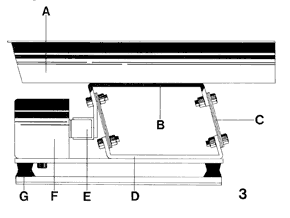
The figure above shows the construction principle of the equipment:
The elements causing the oscillations such as electromagnet (F) and counter core (E), flat springs (C) and oscillating masses (B and D) form the so-called BEM-08 drive base.
The transport element (A), either rail or tube, is attached to this drive base.
The electromagnetic system (F and E) drives the assembly to linear, mechanical and oriented vibrations due to the inclination of the springs.
The vibration frequency is 3600 vibrations per minute (VPM) at 60Hz, or 3000 at 50Hz.
Rubber buffers (G) prevent a transmission of vibrations to supporting structures.
As already mentioned in the Introduction, the hourly flow rate can be regulated from 0 to 100%.
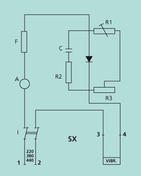
This is achieved through an electronic regulator circuit, which controls the voltage applied to the electromagnetic coil (F).
The higher the applied voltage, the greater the electromagnetic force generated, the greater the vibration amplitude, and therefore the greater the hourly capacity.
The circuit basically consists of a rheostat (voltage regulator), a diode (rectifier of the oscillation, so as to allow only 3600 VPM), and a capacitor-resistance protection circuit (transformer of the counter-current generated by the coil in heat).
The structure of the circuit can be seen in the figure at the side.